
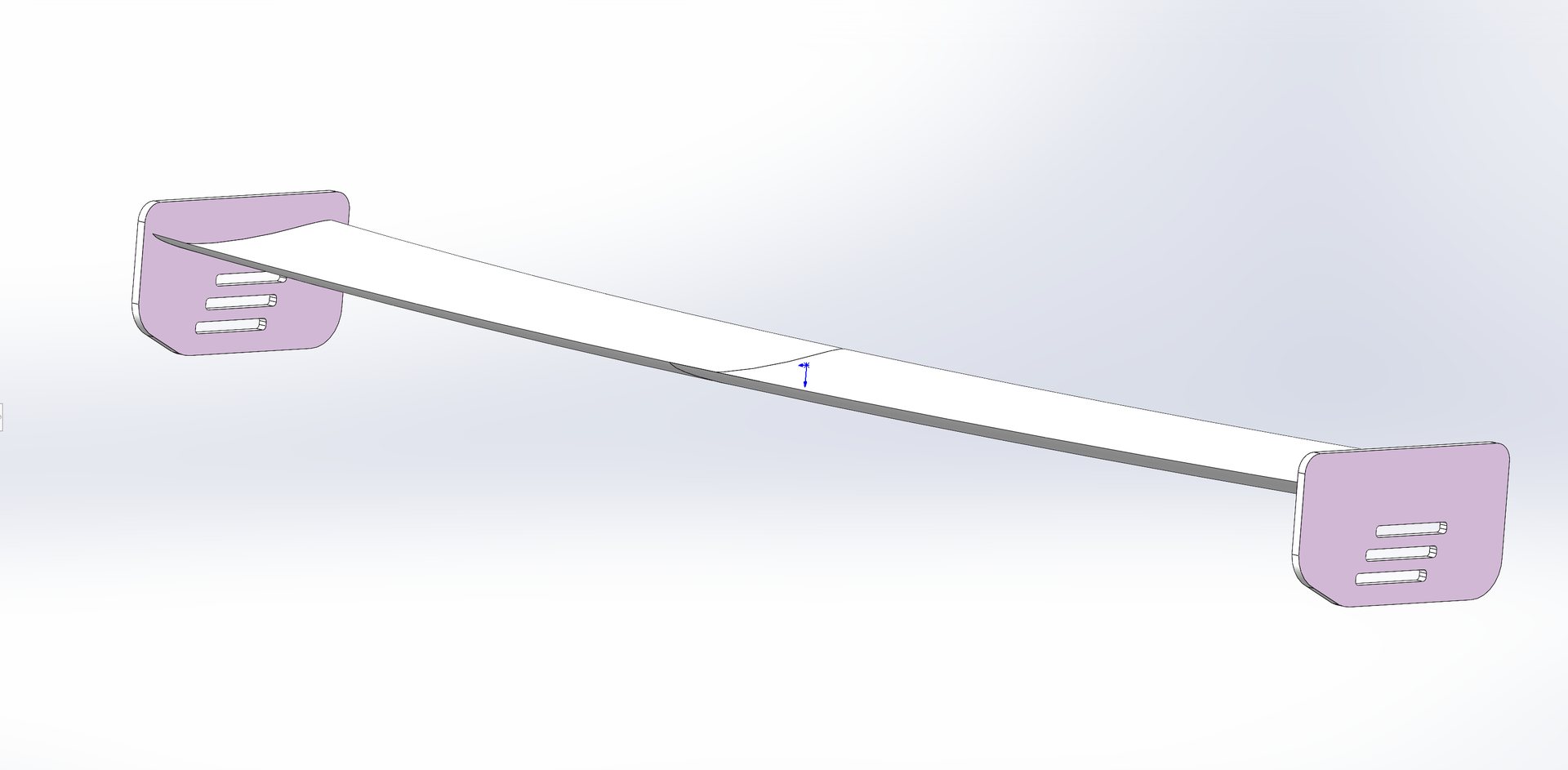
Six months of simulation work is leaving the workstation and heading for the trunk lid. The PB S2000 GT Wing — a single-element, swan-neck-mounted carbon-fiber wing developed entirely in CFD — opens for pre-sale today.
The numbers
The wing was optimized as a system: a one-piece main plane with a blended airfoil profile (mild leading section, high-camber trailing section — fixed geometry, nothing to adjust or service), slotted endplates, and swan-neck mounts that keep the suction surface clean. The result is a downforce curve that stays honest all the way to freeway-plus speeds. All figures below are at the 0° design angle of attack — the as-mounted state:
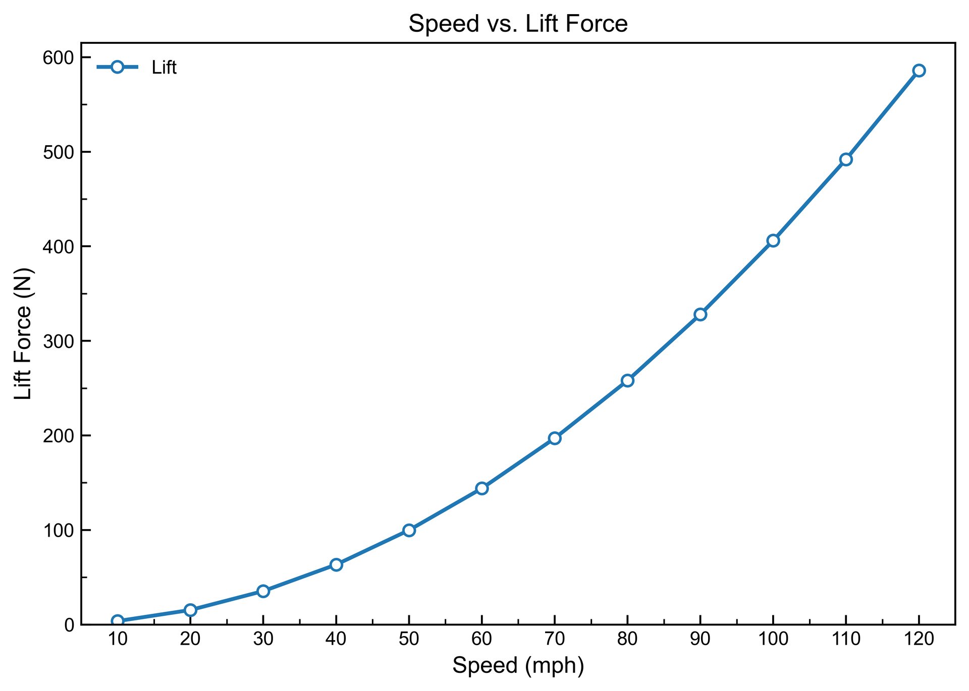
~590 N (60 kgf) of downforce at 120 mph — against a drag penalty of just ~37 N (3.8 kgf):
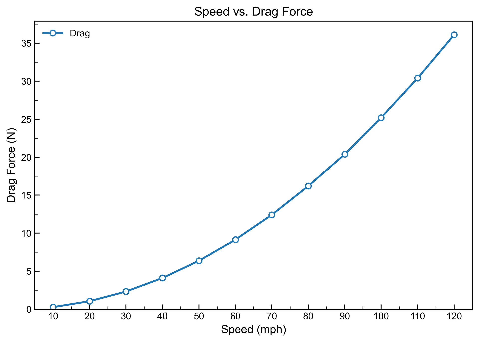
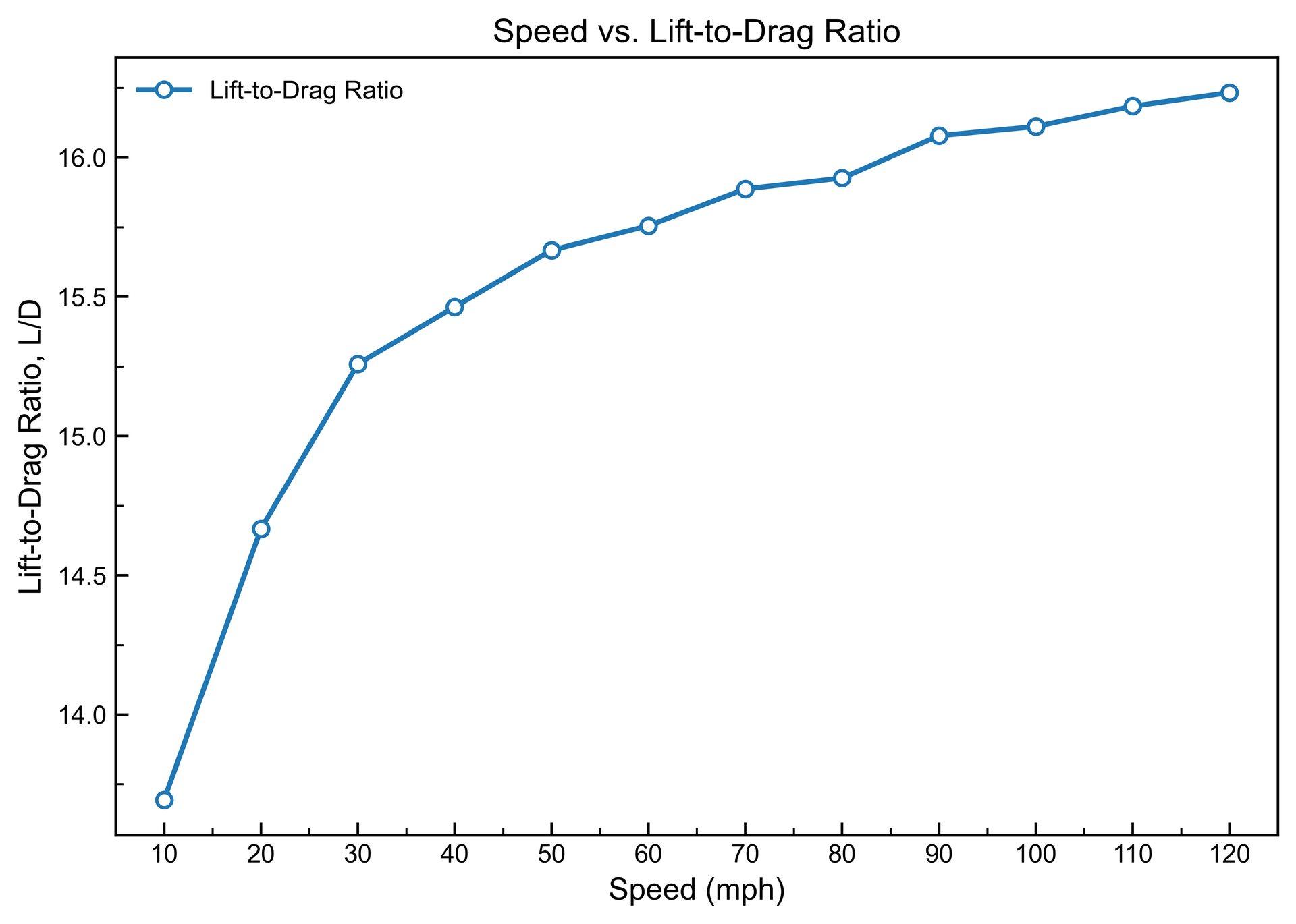
That works out to an L/D of 16.2 at speed, rising from 13.7 at low speed as the wing reaches its design window:
The development loop
Nothing here was sketched and hoped for. The wing was iterated in CFD against the full car — not in a free-air tunnel fantasy — so the numbers above already include the S2000's body wake, roofline flow, and hatch interaction:
Full-car CFD: pressure and velocity fields around the S2000 with the wing fitted. The wing works in the car's wake, so it is developed in the car's wake.
Why the endplates have slots
Look closely at the endplate — those vented slots are not styling. A wing makes downforce from a pressure difference: high pressure above, low pressure below. At the tip, that high-pressure air tries to curl around the endplate edge into the low-pressure side, rolling into a strong vortex. That vortex is wasted energy — induced drag — and flow that separates there is downforce you paid for and didn't get.
The slots bleed a controlled jet of high-pressure air through the endplate. The jet does two jobs: it weakens the tip vortex at its source, and it re-energizes the slow boundary-layer air along the endplate so the flow stays attached at higher wing angles. In the simulation you can see the slot jets organizing the tip flow into a clean, tight structure instead of a diffuse vortex:
Endplate close-up: slot jets accelerating through the vents, rolling the tip flow into a controlled structure.
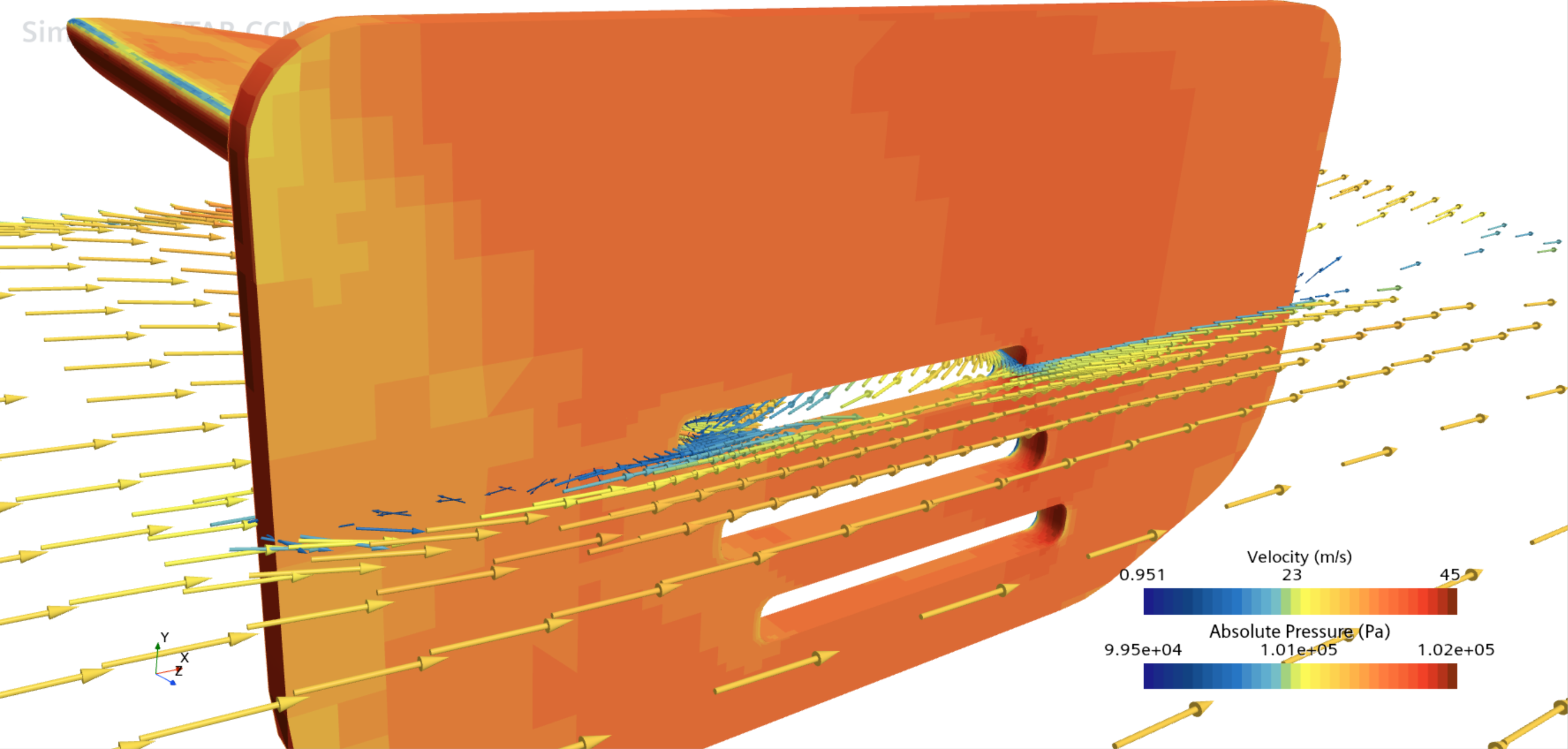
The net effect: the same downforce with measurably less drag — the L/D of 16.2 quoted above is with the slotted endplates fitted.
The hardware
- Autoclave-cured carbon-fiber main plane — one piece, fixed blended profile
- Slotted endplates to manage the tip vortex
- Swan-neck mounts as standard — the high-pressure side takes the hardware, the suction side stays clean
- CNC-machined 6061-T6 aluminum mounting brackets, profiled to the S2000 rear deck
Dimensions (from the production CAD):
| Overall width, incl. endplates | 1,720 mm |
| Wing span between endplates | 1,680 mm |
| Chord | 250 mm |
| Max profile thickness | 32.3 mm (12.9% chord, at 23% chord) |
| Endplate footprint | 290 × 160 mm |
| Planform area | ~0.42 m² |
| Mount height above deck | 350–370 mm (wing sits level with the roofline) |
| Published data measured at | 0° angle of attack |
Pre-sale terms
This is a crowdfunded run. The batch is capped at 150 sets; once 100 sets are pledged, we cut the production steel molds and the build clock starts. Early-bird price is US$990 per set during the pre-sale window.
The wing ships with brackets engineered for the S2000. It fits other cars — but the bracket geometry is car-specific: for any other chassis we redesign the CNC aluminum mounts against your car's rear-end profile before cutting metal. Swan-neck mounting remains the default on every variant.
Questions or custom fitment — write to [email protected] with your chassis and plans for the car.
Discussion